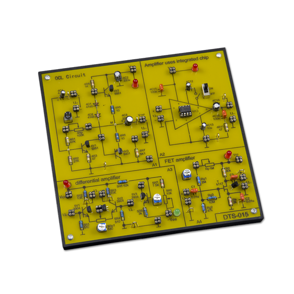
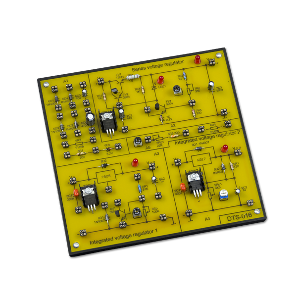
ACL-7000 ANALOGUE TRAINING SYSTEM WITH EXPERIMENTAL BOARD
€754.00 (€927.42 Tax Included)
Analogue training system with experimental board.
4 in stock
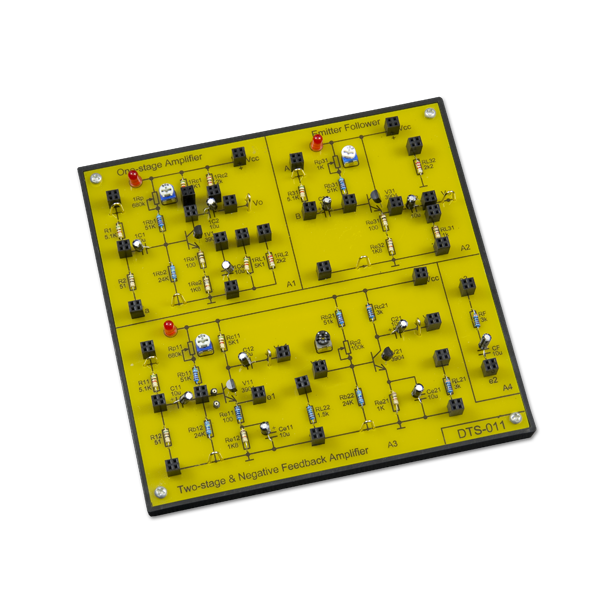
- Four circuit boards form 22 experiments.
- Ideal tool for learning the basics of analog circuits.
- Step-by-step exercises and application.
- Integrated training system, with complete INSTRUCTION.
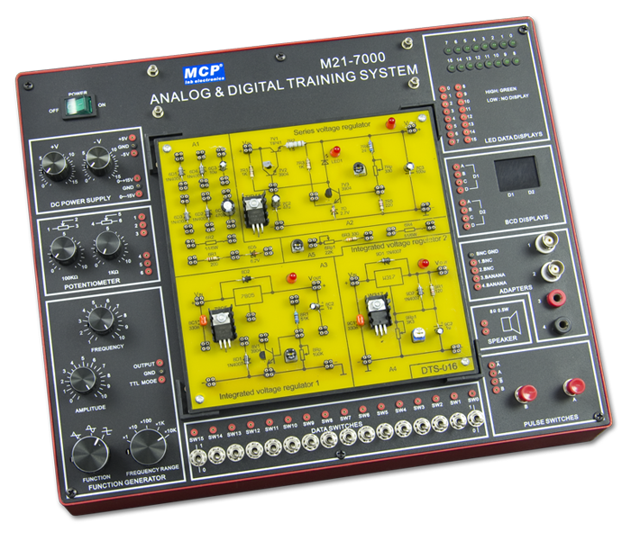
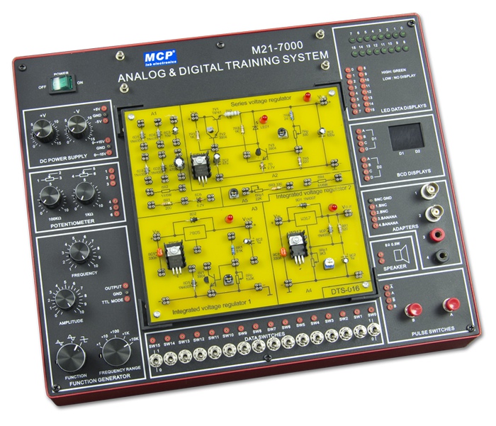
- Combination with M21-7000 digital-analog training system as main unit.
- Step-by-step exercises and application.
- Expandability and flexibility of experiments greatly increased by large breadboard.
- Boards can be changed easily.
The ACL-7000 analog circuit laboratory is a comprehensive and selfcontained system suitable for tuition and experimentation with a range of analog electronics circuits. All necessary equipments such as power supply, signal generator, switches and displays are built-in on the main unit. The 6 circuit boards cover a wide variety of essential topics in the field of analog electronics. It is a time and cost saving device for both students experiment and researchers interested in developing and testing circuit prototypes.
THE FULL LIST OF EXPERIMENTS PERFORMED USING DTS-011 ~ DTS-016
| Experiment 1 Experiment 2 Experiment 3 Experiment 4 Experiment 5 Experiment 6 Experiment 7 Experiment 8 Experiment 9 Experiment 10 Experiment 11 Experiment 12 Experiment 13 Experiment 14 Experiment 15 Experiment 16 Experiment 17 Experiment 18 Experiment 19 Experiment 20 Experiment 21 Experiment 22 |
Monopole Amplifying Circuit Two Stage Amplifier Circuit Negative Feedback Amplifier Circuit Emitter Follower Differential Amplifier Scaling Summing Amplifier Integrator and Differentiator Amplifier Waveform Generator Circuit Active Filter Voltage Comparator Wien Bridge Oscillator Integrated Power Amplifier Rectifier Filter and Parallel Regulation Circuit Series Regulation Circuit Integrated Voltage Regulator RC Oscillator LC Oscillator and Frequency-selective Amplifier Current/voltage Conversion Circuit Voltage/frequency Conversion Circuit Complementary Symmetry Power Amplifier Waveform Conversion Circuit FET Amplifier |
| Catalog Number | 116159 |
|---|
Specifications
MAIN UNIT M21-7000
| SOLDERLESS BREADBOARD | Interconnected with 2820 tie points nickel plated contact,fitted all DIP sizes and all components with lead and solid wire AWG # 22-30 (0.3-0.8mm).It can be changed and replaced for different purpose and can be connected with demonstration panel. Therefore, it is very convenient for both teachers and students. |
| DC POWER SUPPLY | |
| A. Fixed DC output | +5V, 1A |
| B. Fixed DC output | -5V, 1A |
| C. Variable DC output | 0V to +15V, 1A |
| D. Variable DC output | 0V to –15V, 1A |
| POTENTION METERS | |
| A. Variable resistor VR1 | 1kΩ |
| B. Variable resistor VR2 | 100kΩ |
| FUNCTION GENERATOR | |
| Frequency range | 1Hz-10Hz 10Hz-100Hz 100Hz-1kHz 1kHz-10kHz 10kHz-100kHz |
| Amplitude | Sine wave output:0-10 Vpp variable Triangle wave output:0-10 Vpp variable Square wave output:0-10 Vpp variable TTL mode output:4 Vpp |
| TWO DIGITS OF 7 SEGMENT LED DISPLAY | |
| TWO PULSE SWITCH | 2 pcs pushbuttons contain switches debouncer for eliminating the bounce caused by switch from“open” to“close” or from“close” to“open”position. |
| SIXTEEN DATA SWITCHES | 16pcs toggle switches and corresponding output point. When switch is set at “down”position,the output is LO level; contrarily, it is to be HI level while setting at “up”position. |
| SPEAKER | 2-1/2 inch diameter, 8 ohm/0.5W to be used for load. |
| FOUR CHANNEL ADAPTOR | Both of the two banana sockets’ and two BNC jacks’ point tips are changeable. It is suitable for M21-7000 to be connected with peripherals. |
| SIXTEEN BITS LED DISPLAY | 16 red LED’s separate input terminals. The LED will be lighted up when input is at “HI level” ,and it will be turned off when it is at no input or at “LO level”. |
| UNIVERSAL CONNECTOR FIXED HOLDER | |
| It reserves universal connector fixed holder on the panel in order to be connected with various universal connectors, which are available |
(1) Straight header 60 pin |
| (2) Card edge connector 2.54mm 62pin | |
| (3) D sub25 pin connector, male & female | |
| (4) Card edge connector 3.96mm 56pin | |
| (5) Dip sockets connector 28 pin & 40 pin | |
1. Accessories
(1) Power cord
(2) Pin leads: 10cm 20pcs, 20cm 20pcs
(3) User manual+ instruction of analog circuit experimentations
2. INPUT VOLTAGE: 110~127VAC±10% 60Hz, 220~240VAC±10% 50Hz Switchable
3. DIMENSIONS:
(1) Main unit (W×H×D): 258×95×334mm
(2) Circuit board: 165×170mm
4. WEIGHT:
(1) Main unit: 4.5kg
(2) Circuit board: 0.4kg×6
Catalog Card
DownloadRelated products
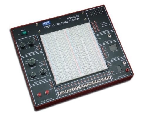
M21-5000 DIGITAL TRAINING SYSTEM
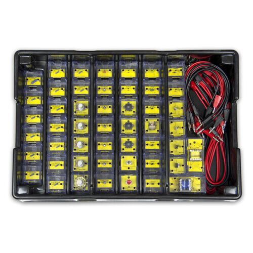
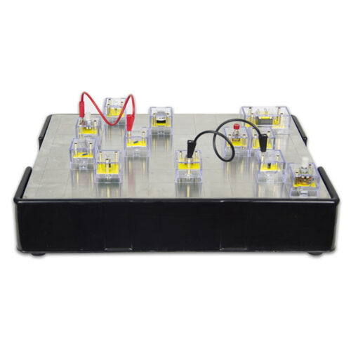
F1-1 BASIC ELECTRONIC CIRCUIT TRAINING SYSTEM

F20-101 TRANSPARENT ELECTRIC COUNTER BOX EXPERIMENT BOX
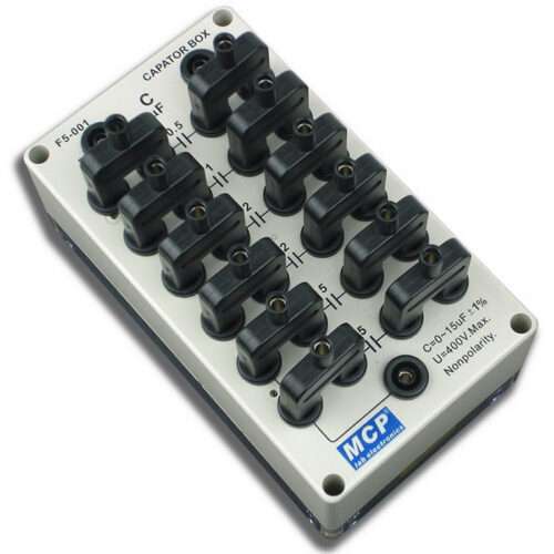
F5-001 CAPACITOR BOX WITH JUNCTION
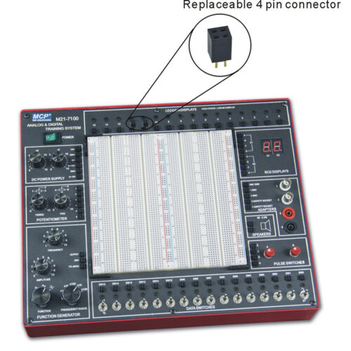

M21-7100 DIGITAL AND ANALOGUE TRAINING SYSTEM WITH REPLACEABLE CONNECTOR


M21-7100A DIGITAL AND ANALOGUE TRAINING SYSTEM WITH UNIVERSAL COUNTER FUNCTION
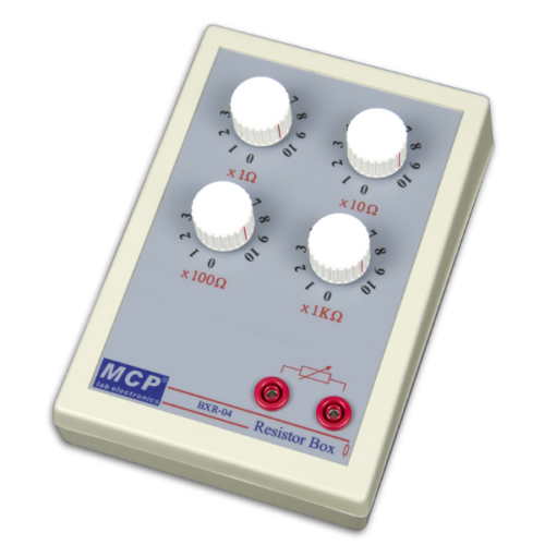
BXR SERIES RESISTOR BOX, DECADE BOX
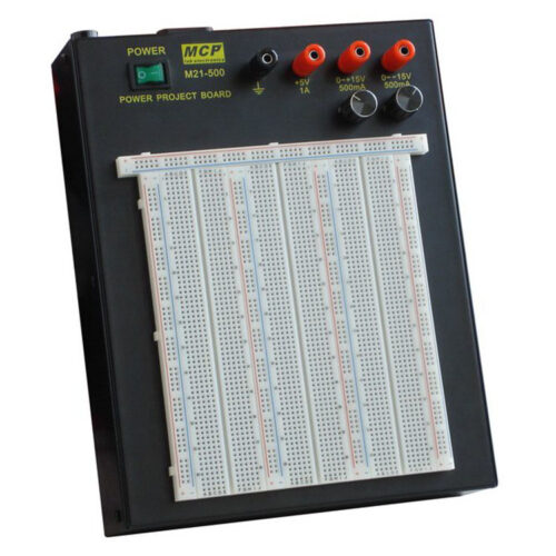
M21-500 POWER PROJECT BOARD DC POWER SUPPLY BREADBOARD
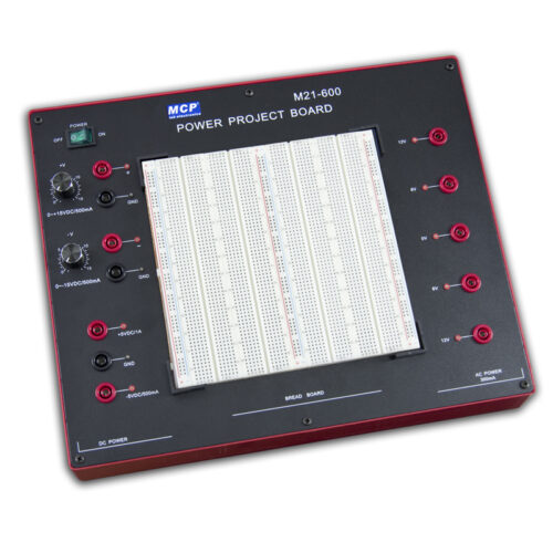
M21-600 POWER PROJECT BOARD WITH BOTH AC AND DC POWER SUPPLY
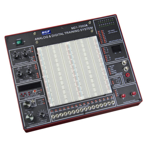
M21-7000A DIGITAL AND ANALOGUE TRAINING SYSTEM WITH UNIVERSAL COUNTER FUNCTION
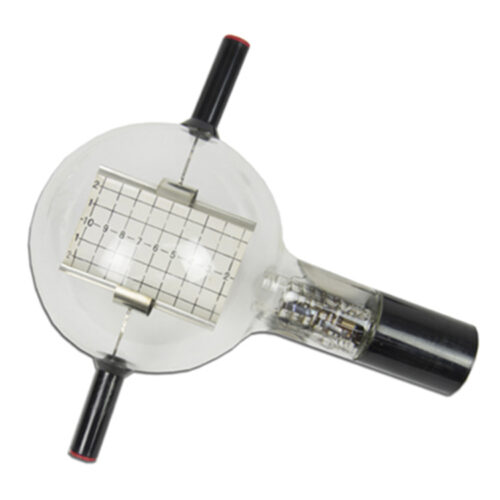
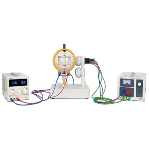
ELECTRON DEFLECTION TUBE SYSTEM
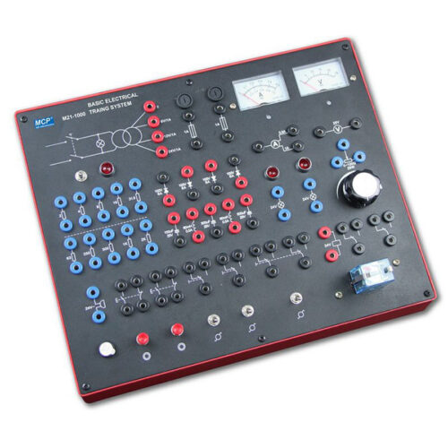
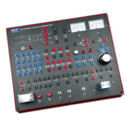
M21-1000 SERIES BASIC ELECTRICAL TRAINING SYSTEM
